Dimensional Stability in Flexible PCBs
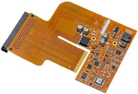
A flexible printed circuit board (PCB) can flexibly adapt to a wide range of shapes, increasing functionality and durability in electronic devices. They are also lighter, take up less space, and can withstand vibrations and other disruptions from their environment. Using flexible PCBs reduces assembly costs, as well as time and effort. However, implementing a flex or rigid-flex PCB requires careful planning to ensure the physical and electrical integrity of the design.
One issue that may affect the quality of a flex or rigid-flex PCB is dimensional stability. The nature of a flexible pcb fabrication process causes the polyimide film to undergo stress, which can cause small dimensional changes in the finished product. This is a natural phenomenon that happens due to residual stresses from manufacturing processes and the normal coefficient of thermal expansion for the film.
The dimensional stability of a flex or rigid-flex printed circuit board depends on several factors, including the thickness and type of materials used. To reduce these alterations, the PCB fabricator must start with high-quality materials from a reliable supplier, and must carefully inspect the laminates and prepreg plies. Then, the layer stackup should be arranged to meet the desired design specifications. Finally, the laminates and prepregs should be pressed and cured under controlled heat and pressure to achieve high-quality results.
For a flex or rigid-flex PCB, the layers of the inner flex ribbon are placed between rigid sections. This can help avoid stress concentrations around holes or components and minimize the risk of a flex PCB breaking apart from the mechanical stresses it experiences during bending. This arrangement can also simplify the manufacturing and assembly process, as it avoids exposing the inner flex ribbon to the outer copper layer plating and etching steps.
How to Ensure Dimensional Stability in Flexible PCBs
Dimensional changes in a flex or rigid-flex PCB can be caused by numerous processing effects, such as lamination, copper electroplating, thermal cycling, and mechanical stresses. Each of these can affect the thickness of the resulting PCB by changing the material’s physical properties. In addition, the tolerances set up during the flex drawing phase can affect the final thickness of a flex or rigid-flex board.
To keep the flex or rigid-flex PCB’s dimensions consistent throughout production, PCB fabricators must establish tolerances on all copper layers except those that are used for pads and vias. This ensures that the final product will comply with all flex drawings and design rules.
Another way to ensure a flex or rigid-flex PCB’s dimensional consistency is by making sure that the board is designed for its calculated bend radius. This can be done by avoiding overlapping ground planes and traces, and by incorporating a flexible design with large radii to help reduce conductor strain.
Another factor to consider is the soldering method used for the flex or rigid-flex PCB. Different methods require varying temperatures and solder alloys, which can have a significant impact on the flex or rigid-flex PCB’s quality. Using a reflow or selective soldering technique can minimize the temperature and metal content of the solder, which will help protect the flex or rigid-flex PCBs and components from damage.